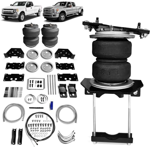
VIGOR 89352 Air Spring Bags Suspension Kit
Introduction
The purpose of this publication is to assist with the installation and maintenance of the 7X 89352 air spring kits. All 7X 89352 kits utilize sturdy, reinforced, commercial-grade single or double, depending on the kit, convolute bellows. The air springs are manufactured like a tire with layers of rubber and cords that control growth. 7X 89352 kits provide up to 5,000 pounds (2,268kg) of load-leveling support with air adjustability from 5-100 PSI (.34-7BAR). It is important to read and understand the entire installation guide before beginning installation or performing any maintenance, service or repair.
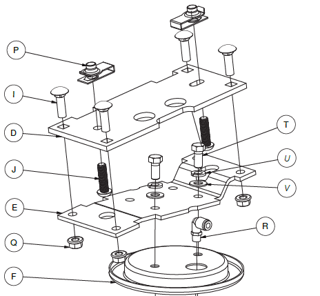
Installation Diagram
Hardware and Tools Lists
Common Parts Included in All 3 Kits Unique Parts in Each Kit.
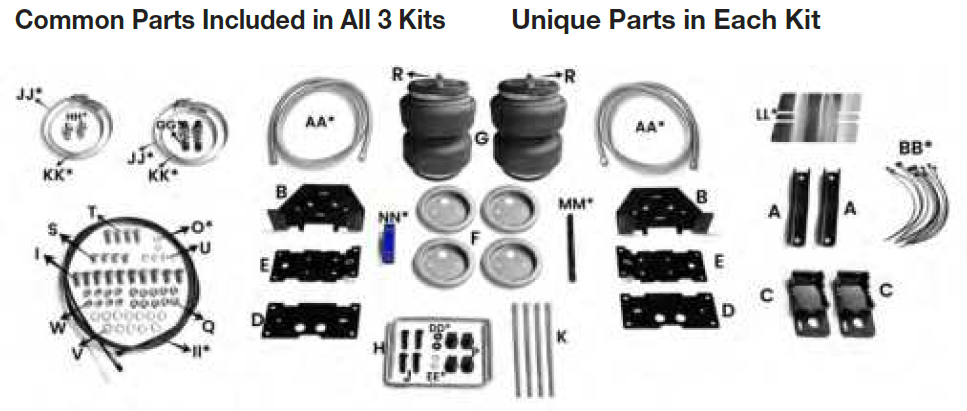
| Item | Description | Qty |
| A | Clamp bar | 2 |
| B | Lower bracket, main plate | 2 |
| C | Lower bracket, cup | 2 |
| D | Upper bracket, frame | 2 |
| E | Upper bracket, air spring | 2 |
| H | U-bolt | 2 |
| I | 3/8″-16 x 1″ Carriage bolt | 10 |
| J | M10-1.5 x 35 Button-head cap screw | 4 |
| K | 3/8″-16 x 10″ Carriage bolt | 4 |
| O* | M8 Stainless steel flat washer | 2 |
| P | M10-1.5 Universal nut | 4 |
| Q | 3/8″-16 Serrated flange lock nut | 10 |
| V | Flat washer | 12 |
| W | 3/8″-16 Nylon lock nut | 8 |
| DD* | Rubber washer | 2 |
| EE* | Stainless steel star washer | 2 |
| F | Roll plate (stainless steel) | 4 |
| G | Air spring with jounce bumper | 2 |
| R | AN-type fitting | 2 |
| S | 3/8″-24 x 3/4″ Stainless flat-head socket-cap screw | 4 |
| T | 3/8″-24 x 7/8″ Stainless steel hex-cap screw | 4 |
| U | 3/8″ Stainless steel lock washer | 4 |
| AA* | Stainless steel braided air line | 2 |
| BB* | Zip tie | 12 |
| GG* | Schrader valve w/ cap & nut | 2 |
| HH* | AN to PTC fitting | 2 |
| II* | Air line assembly | 1 |
| JJ* | Worm clamp(64-114) | 2 |
| KK* | Worm clamp(65-89) | 2 |
| LL* | Thermal Board(190*127) | 1 |
| MM* | Thermal sleeve(∅12,L =195mm) | 1 |
| NN* | Air hose cutter | 1 |
NOTATION EXPLANATION
Hazard notations appear in various locations in this publication. Information which is highlighted by one of these notations must be observed to help minimize risk of personal injury or possible improper installation which may render the vehicle unsafe. Notes are used to help emphasize areas of procedural importance and provide helpful suggestions. The following definitions explain the use of these notations as they appear throughout this guide.
TOOLS LIST
- Standard and metric open-end or box wrenches ………………………… SET
- Ratchet …………………………………………………………………………………………………..1
- Standard and metric sockets ……………………………………………………………….SET
- 5/16″ drill bit (very sharp) ………………………………………………………………1
- 9/16″ Crow’s foot adapter ……………………………………………………………..1
- 9/16″ ratchet combo wrench ………………………………………………………….1
- Heavy-duty drill ……………………………………………………………………………1
- Torque wrench ……………………………………………………………………………..1
- Standard and metric hex-key wrenches ………………………………………….1
- Flat-tip screwdriver ……………………………………………………………………….1
- Hose cutter, razor blade, or sharp knife …………………………………………..1
- Hoist or floor jacks ……………………………………………………………………….1
- Safety stands ……………………………………………………………………………….2
- Safety glasses ……………………………………………………………………………..1
- Air compressor or compressed air source ……………………………………….1
- Spray bottle with dish soap/water solution ………………………………………1
Installing the System
PREPARING THE VEHICLE
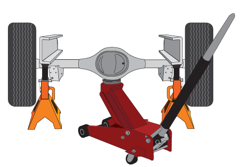
- Raise the vehicle and support it, using safety stands or equivalent, so that the axle can be safely lowered away from the frame. This needs to be done in order for the air spring assembly to be put into position between the axle and frame
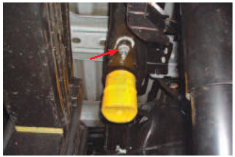
- Unbolt and remove the jounce bumper assembly from under the frame on both sides
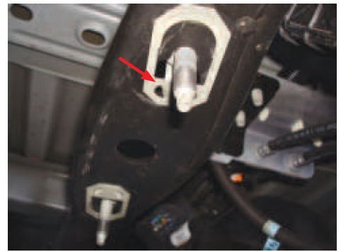
- Remove the clip-in studs by prying on the hinged end with a screwdriver. Pull all four (two from each side) out from the frame
- Install the universal nuts (P) into the frame rail, lining up the holes in the frame and the threads in the nuts so that a bolt can be installed
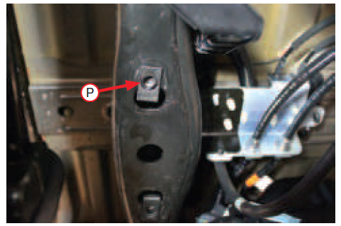
TECH TIP
- A flat-tip screwdriver works well in installing the universal nut into position.
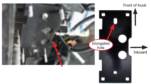
- Insert the 3/8″-16 x 1″ carriage bolts (I) into the upper frame brackets (D).
- Install the upper bracket onto the frame using the M10-1.5 x 35mm button head cap screws (J).
- The slot on the side of the bracket should be inboard of the frame rail
- The elongated hole should be toward the front of the truck. Torque hardware to 38 lb.-ft. (52Nm).
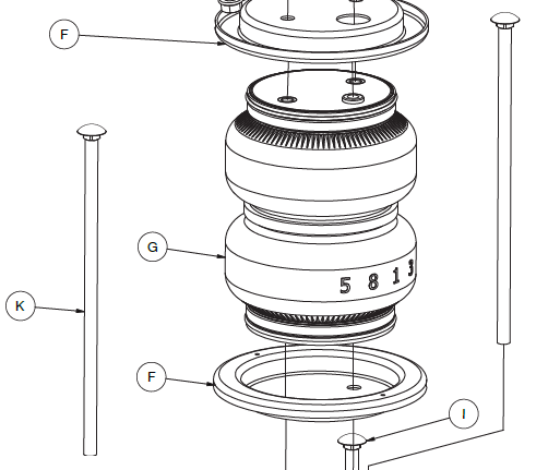
ASSEMBLING THE AIR SPRINGS
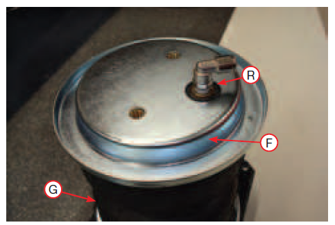
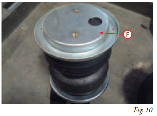
- Set a roll plate (F) on top of the air spring (G). The radiused, or rounded, edge of the roll plate should be toward the air spring so that it is seated inside the roll plate
- Install the 90 degree swivel fitting (R) into the port on top of the air spring, finger-tight plus 1 1/2 turns.
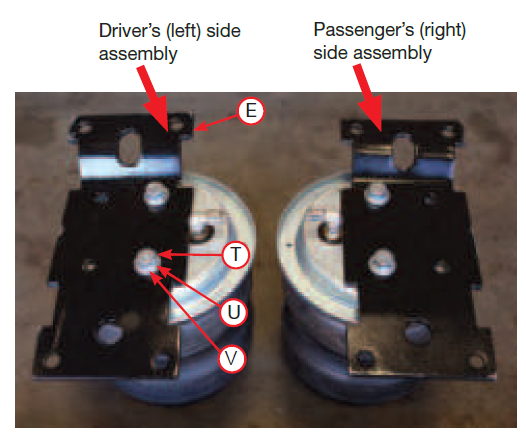
- Set the upper air spring bracket (E) onto the top of the air spring using one set of holes with the 3/8″-24 x 7/8″ hex-cap screw (T), 3/8″ lock washer (U) and 3/8″ flat washer (V)
- Install the remaining air spring bracket onto the remaining air spring, using the opposite holes from those that were previously used.
- This makes the air spring assemblies into left- and right-hand units. Torque the hardware to no more than 20 lb.-ft. (27Nm).
- Fip the assemblies over and set a roll plate (F) onto the bottom of the air springs
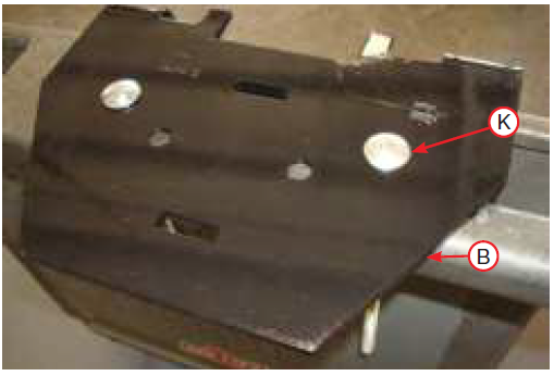
- Insert two 3/8″-16 x 10″ carriage bolts (K) through the square holes in the lower bracket main plate (B)
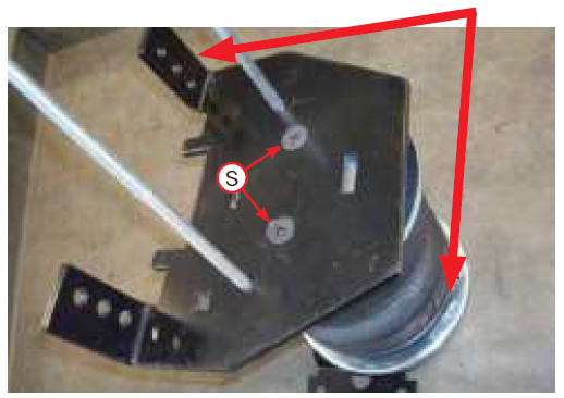
- Set the lower bracket main plate assemblies onto the air springs with the roll plates installed. Attach with the 3/8″-24 x 3/4″ flat-head socket-cap screws (S)
Torque the hardware to no more than 20 lb.-ft. (27Nm).
NOTE
The flange on the lower bracket must be on the opposite side of the fitting that is located on the top of the air spring.
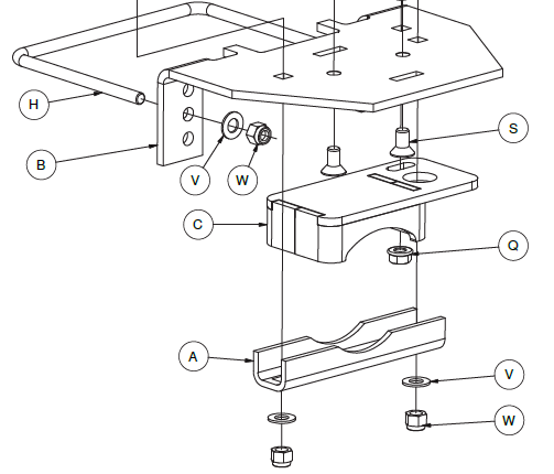
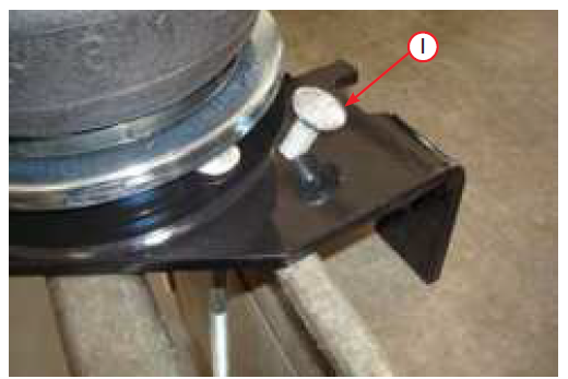
- Insert the 3/8″-16 x 1″ carriage bolt (I) through the top of the lower bracket.
- Flip over the assembly and install the lower bracket cup (C) onto the lower bracket main plate over carriage bolt and cap with serrated flange lock nut
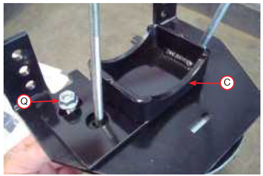
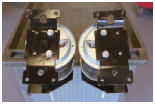
- Snug bolt down but leave loose enough for the bracket to move freely in slot.
- the driver’s (left) side and passenger’s (right) side assemblies.
INSTALLING THE AIR SPRING ASSEMBLIES
- With the vehicle supported by safety stands, drop the axle or raise the body so that the assemblies can be put into position in between the axle and frame.
- Set the driver’s (left) side and passenger’s (right) side assemblies into position so that the lower bracket cup rests on the jounce bumper strike plate for single rear wheel (SRW)or the axle for dual rear wheel (DRW)
NOTE
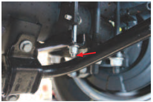
If there is a sway bar, insert the carriage bolts through the Clamp Bar (A) while setting the assemblies into position over the axle
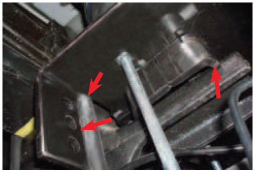
- Push the lower bracket so that it is flush against the leaf spring stack. The flanges on the lower bracket main plate should lock on the sides of the U-bolt
NOTE
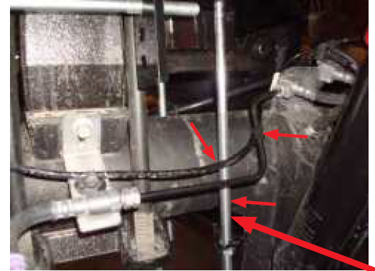
On the driver’s (left) side, the long carriage bolt in the lower bracket main plate should be located between the hard brake line and axle.On the passenger’s (right) side, the carriage bolt should be located on the backside of the brake line
- Install the U-bolts (H) around the stock U-bolt/leaf spring assembly and insert through the topmost holes in the lower bracket main plates
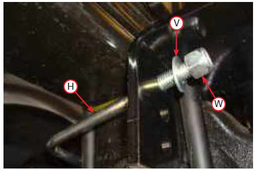
- Cap with the 3/8″ flat washer (V) and 3/8″ nylon lock nuts (W). Snug bolts evenly, just enough to hold the lower bracket main plate flush against the stock U-bolts.
- Before proceeding, ensure the 90 degree fittings each point inboard toward the center of the vehicle.
- While raising the axle or lowering the body of the vehicle, align the previously installed upper frame bracket carriage bolts with the air spring bracket holes so the carriage bolts protrude through the air spring bracket.
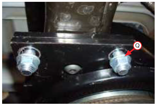
- Cap the carriage bolts with the 3/8″ serrated flange lock nuts (Q) .Snug the bolts down first then torque to 31 lb.-ft. (42Nm). Finish raising the axle or lowering the body and remove safety stands.
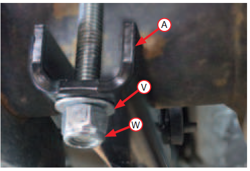
- If not completed, set the lower clamp bars (A) over the carriage bolts located under the axle .Attach with the 3/8″ flat washers (V) and 3/8″ nylon lock nuts (W). Evenly torque the lower clamp bar hardware to 16 lb.-ft. (22Nm). Finish tightening the U-bolt hardware previously snugged by torqueing to 10 lb.-ft. (14Nm).
TECH TIP
For sway bar applications it is acceptable to tighten the front carriage bolt hardware down more than the rear to gain more clearance on the sway bar. Also, it may be necessary to use a 9/16″ crows foot adapter to properly torque the hardware.
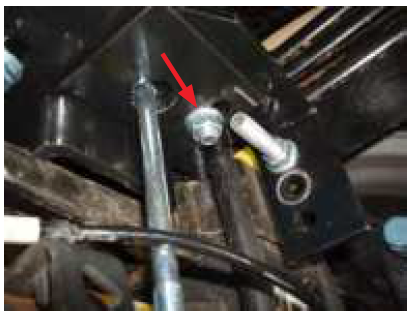
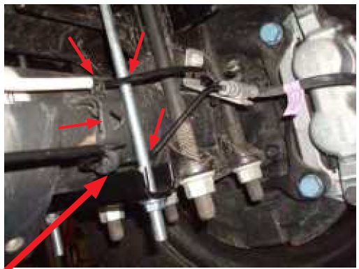
- On vehicles that have a sway bar, cut the front carriage bolt just below the nut, so it does not contact the sway bar
- Torque the nut (Q) to 32 lb.-ft. (43Nm) on both sides
- Once the lower brackets are secured, ensure the brake and ABS lines are not rubbing against the lower bracket carriage bolt. If necessary, pull or push the hard brake line away and tie off the ABS line to gain clearance.
NOTE
On the passenger side, it may be necessary to pull the ABS tree mount out of the top of the bracket. Re-attach by installing the tree mount to the back
CAUTION
PUSH THE HARD BRAKE LINE AWAY FROM THE LOWER BRACKET CARRIAGE BOLT IF THE LINE IS RESTING ON IT
Installing the Air Lines
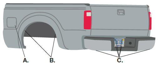
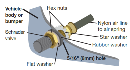
Air lines are routed from the air springs to Schrader valves 7X 89352 air lines come in two styles: nylon and braided stainless steel. Begin by choosing locations for the Schrader valves and drill a 5/16″ (8mm) hole, if necessary For 7X 89352 Ultimate Plus kits, the recommended location for the Schrader valves is the rear bumper area or license plate.
- Inside fuel tank filler door
- Inside rear wheel wells
- License plate or rear bumper area*
CAUTION
KEEP AT LEAST 6″ (150MM) OF CLEARANCE BETWEEN ALL AIR LINES AND THE EXHAUST SYSTEM. AVOID SHARP BENDS AND EDGES.
INSTALLING NYLON AIR LINES
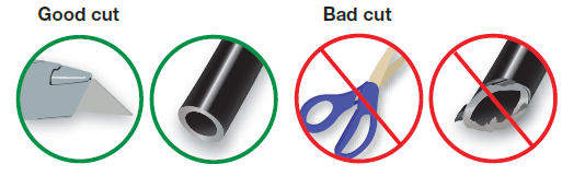
- Cut the air line in half. Make clean, square cuts with a razor blade or hose cutter .Do not use scissors or wire cutters.
- Use zip ties to secure the air line to fixed points along the chassis. Do not pinch or kink the air line. The minimum bend radius for the air line is 1″ (25mm). Leave at least 2″ (51mm) of slack in the air line to allow for any movement that might pull on the air line.
- Install the Schrader valve in the chosen location
- When encountering difficulty in inserting the endotracheal tube, the following actions can be attempted:
- Use sandpaper to gently smooth the outer edge of the tube’s opening, creating a small rounded edge, which facilitates the insertion of the tube.
- Apply a small amount of lubricant (such as grease or beeswax) to the tube’s opening to facilitate smooth insertion into the trachea.
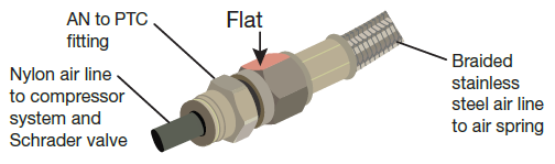
INSTALLING BRAIDED STAINLESS STEEL AIR LINES
CAUTION
KEEP THE AIR LINE AWAY FROM THE FUEL LINE, BRAKE LINES AND ELECTRICAL WIRES.
- Use zip ties to secure the air line to fixed points along the chassis every 6″ to 8″ (152 to 203mm). Leave at least 2″ (51mm) of slack to allow for any movement that might pull on the air line.
- Tighten the air line hex nut finger-tight, then use 2 wrenches to turn 1 additional flat (1/6 of one full turn). Do not over tighten .The easiest way to tighten the fitting is off the vehicle. Install the Schroeder valve in the chosen location.
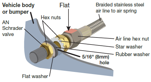
- Coil and secure any excess air line in an area where it will not be susceptible to damage. The braided stainless steel air line cannot be trimmed.
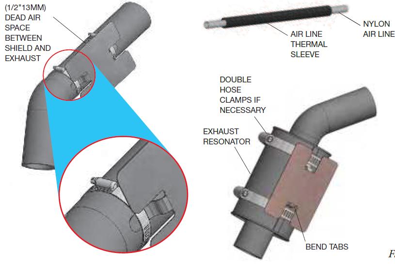
INSTALLING THE HEAT SHIELD
- Attach the metal heat shield to the exhaust where it is closest to the air spring. Slide the air line thermal sleeve over the nylon air line and place it where the air line is closest to the exhaust
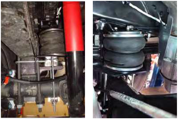
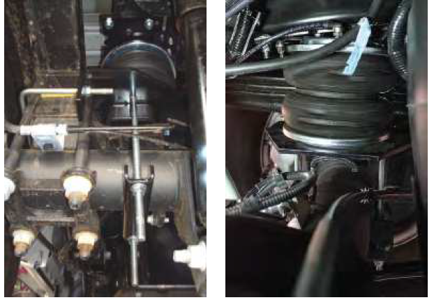
Finished Installation
These images show the finished installation of both sides for the F-250 and F-350 single rear wheel (SRW) applications
INSTALLATION CHECKLIST
- Clearance test — Inflate the air springs to 40-60 PSI (2.8-4.1BAR) and make sure there is at least 1/2″ (13mm) clearance from anything that might rub against each air spring. Be sure to check the tire, brakes, frame, shock absorbers and brake cables.
- Leak test before road test — Inflate the air springs to 40-60 PSI (2.8-4.1BAR) and check all connections for leaks. All leaks must be eliminated before the vehicle is road tested.
- Heat test — Be sure there is sufficient clearance from heat sources, at least 6″ (152mm) for air springs and air lines. If a heat shield was included in the kit, install it. If there is no heat shield, but one is required,Contact Us.
- Fastener test — After 500 miles (800km), recheck all bolts for proper torque.
- Road test — The vehicle should be road tested after the preceding tests. Inflate the air springs to recommended driving pressures. Drive the vehicle 10 miles (16km) and recheck for clearance, loose fasteners and air leaks.
- Operating instructions — If professionally installed, the installer should review the operating instructions with the owner. Be sure to provide the owner with all of the paperwork that came with the kit.
MAINTENANCE AND USE GUIDELINES
- Check air pressure weekly.
- Always maintain normal ride height. Never inflate beyond 100 PSI (7BAR).
- If the system develops an air leak, use a soapy water solution to check all air line connections and the inflation valve core before deflating and removing the air spring.
CAUTION
- FOR SAFETY AND TO PREVENT POSSIBLE DAMAGE TO THE VEHICLE, DO NOT EXCEED MAXIMUM GROSS VEHICLE WEIGHT RATING (GVWR) OR PAYLOAD RATING, AS INDICATED BY THE VEHICLE MANUFACTURER.
- ALTHOUGH THE AIR SPRINGS ARE RATED AT A MAXIMUM INFLATION PRESSURE OF 100 PSI (7BAR), THE AIR PRESSURE ACTUALLY NEEDED IS DEPENDENT ON LOAD AND GROSS VEHICLE WEIGHT RATING.
CUSTOMER SERVICE
If you have any questions about this product, please contact us below:
- Email: support@vigorairride.com
Thank you very much!
VIGOR 89352 Air Spring Bags Suspension Kit Installation Guide
FAQs
How much time does it take to install?
For novice installations, it takes two to four hours; for seasoned users, it takes one to two hours.
Do I have to take off my wheels in order to install them?
Yes, in order to properly access the suspension, the front and rear wheels must be removed.
Does this kit require a lift to install?
Yes, however before installing brackets, you’ll need to jack up the car to release suspension stress.
Where should the air fill valves be mounted?
Typical spots include the bumper, wheel well, and license plate region. If necessary, drill a small hole
For everyday driving, what PSI should I set?
Unloaded, 15–25 PSI; towed/hauling, 35–50 PSI. Adapt to the comfort of the trip.