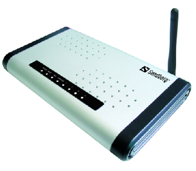
Sandberg G54 Wireless Router
Introduction
Sandberg Wireless G54 Router allows you to share a broadband connection and local area network connection using both wireless and wired connections. The Sandberg Wireless G54 Router is easy to confi gure thanks to its user-friendly web interface. Its features include a range of security set-tings that you can confi gure to prevent uninvited guests. The router works with ADSL, xDSL, FWA and cable modem connections that support one of the four protocols Ethernet, PPPoE or PPTP or L2TP. Your Internet service provider can tell you whether your Internet connection is using one of these four standards.
System requirements
- Internet connection supporting Ethernet, PPPoE, PPTP or L2TP (with RJ45 connector).
- One or more computers with Ethernet adapter or Wireless Ethernet adapter
Specifications
- Supports cable modem, ADSL/xDSL, FWA and Ethernet bridges
- IEEE 802.11g/b Access Point
- Wi-Fi compatible
- Range indoor: Up to 50 meters
- Range outdoor: Up to 250 metros
- Web browser management
- Built-in DHCP.
- Simultaneous use of one public IP address with NAT
- Supporting multiple WAN IP addresses
- SPI Anti-DoS Firewall features
- Supports 64/128/152 Bit Key Length WEP Encryption, WPA
(TKIP, IEEE 802.1x). - Security log
- Supports Virtual server/DMZ, WDS Bridge, Special Applications support (Port Triggers), UPnP, DDNS, PPTP and L2TP VPN Pass Though.
- Obtain WAN IP by PPPoE/Static IP/PPTP/DHCP/L2TP/Telstra Big Pond
- System Status (Port Connectivity, DHCP, MAC/IP Mapping)
- Up to 40 Mbit/s throughput
- 4 100BASE-TX LAN ports
- 1 10BASE-T WAN port
- IEEE802.3x fl ow control
- 12 Status LEDs
- Reset button
- 2 MB NOR fl ash
- 16 MB SDRAM
- ADMtek 5120 (175MHz MIPS R4000) CPU
- Inprocomm mini-PCI Card (IEEE 802.11g) RF Module
- 12V DC, 1A Linear power adapter
- RP-SMA detachable antenna
- Firmware upgradeable
Installing the router
Role of the router on the network
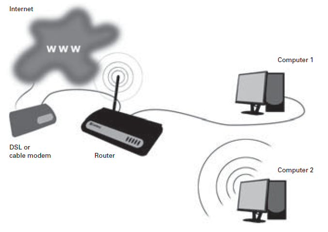
A router acts as a connection point between two networks. A router is generally used to connect a local area network with multiple computers to the network of an Internet service provider. In other words, a router allows several computers to share an Internet connection. The Sandberg Wireless G54 Router is wireless, meaning that computers with wireless network cards can connect to it without the use of cables.
Internet
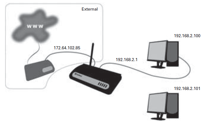
- As the router’s role is to create a bridge between two networks, it has one IP address for each network.
- One IP address represents the router on the Internet and is called the external IP address, and the other represents the router on the local area network and is called the internal IP address.
- Each of the computers on the local area network also has its own IP address.
- This can be allocated automatically by the router (using the router’s DHCP function) or it can be specifi ed manually on each computer.
- 172.64.102.85 is the router’s external IP address.
- When communicating with a computer over the Internet, it will be this address that the computer ‘sees’, regardless of which computer on the local area network is being used.
- The external IP address can either be dynamic or fi xed, depending on the type of subscription set up with the Internet service provider.
- A dynamic IP address is one that is allocated by the Internet service provider, but it is not necessarily the same address all the time. A fi xed IP address always remains the same.
- 192.168.2.1 is the router’s internal IP address. This is the address of the router on the local area network, the one that all the computers on the network connect to in order to access the Internet.
- 192.168.2.100 is the IP address of a computer on the network. This can either be defi ned in Windows or be automatically allocated by the router.
- 192.168.2.101 is the IP address of a computer on the network. This can either be defi ned in Windows or be automatically allocated by the router.
Connecting the router

The router can function both as a router and an access point. The connection mode used with the router depends on how it is intended to function on the network.
- Router – Used if the Internet connection is to be shared between multiple computers, either wirelessly, with cables, or both.
- Access Point – Used if the Internet connection is already shared between multiple computers,
e. g. via a router, and wireless access to the Internet is required. In this case, the role of the router is to provide wireless access to the existing router. - Connect the electrical plug to a mains socket and the small round connector on the power lead to the 12VDC socket on the router. Check that the “Power” lamp lights up.
- If you will be using the router function, connect the router’s WAN port to your existing ADSL/broadband connection using a network cable.
- If you will be using the access point function, connect a network cable from the existing network (typically the existing router) to port 1, 2, 3 or 4 on the router.
- Screw the antenna fi rmly into the thread on the far right. The antenna can be folded upwards to increase the signal strength.
- Connect up to four computers to the ports marked 1 to 4 on the router. If you will only be connecting wirelessly, skip this step.
- Start the connected computers.
Lamp indications
| Lamp indications
LED |
Colour |
Status |
Status |
| PWR | Green | On | The router is on. |
| WLAN-G | Green | On Flashing Off | Wireless connection is active. Wireless connection transmitting data. Wireless connection is inactive. |
| WAN – 10/100M | Green | On Off | 100 Mbit/s connection active. 10 Mbit/s connection active. |
| WAN – LNK/ACT | Green | On Flashing Off | WAN port connected.
WAN port transmitting data. WAN port disconnected. |
| LAN – 10/100M | Green | On Off | 100 Mbit/s connection active. 10 Mbit/s connection active. |
| LAN – LNK/ACT | Green | On Flashing Off | LAN port connected.
LAN port transmitting data. LAN port disconnected. |
Positioning and installation of the router
Drill template
- To ensure the best possible wireless signal conditions, the router should be placed centrally in relation to the devices connecting wirelessly to it.
- The package includes an installation kit containing four rubber feet, two screws and two rawlplugs. The rubber feet can be stuck to the base of the router to stand it on a fl at surface.
- If you wish to wall-mount the router, drill two holes in the wall 14 centimetres (5.51 inches) apart.
- At the back of this manual there is a drill template that you can cut out and use to ensure the holes are the correct distance apart.
- On the back of the router there are two sets of brackets, allowing it to be mounted with the connectors facing up or down.
Setting up the router
Configuring the computer’s network settings
To access the router confi guration, you need to set up the computers on the same network as
the router. In other words, the computers must be set up to have their IP addresses automatically allocated by the router.
Windows® XP
- Click [Start], [Control Panel] and then [Network and Internet Connections]. Double-click
[Network Connections]. - Double-click [LAN Connection]. Then click [Properties].
- Double-click [Internet Protocol (TCP/IP)] and select Obtain an IP address automatically and Obtain DNS server address automatically.
- Click [OK] and close the Local Area Connection Properties dialog box by clicking [OK].
- The IP address will now be active.
Windows® 2000
- Click [Start], then [Settings] and [Dial-up and Network Connections].
- Double-click [LAN Connection]. Click [Properties].
- Double-click [TCP/IP] and select Obtain an IP address automatically and Obtain DNS server address automatically.
- Click [OK] and close the Local Area Connection Properties dialog box by clicking [OK].
Windows® 98SE/Me
- Click [Start], [Settings], [Control Panel]. Double-click the [Network] icon.
- Double-click [TCP/IP] and select Obtain an IP address automatically.
- Click [OK] and close the Network dialog box by clicking [OK].
Restart the computer.
The IP address will now be active.
Configuring the router
NB:
If you will be using the router as an access point only, the following steps can be skipped. However, the router’s wireless security function should be enabled. (See section 2.3) If you will be using the router wirelessly, the computer must be connected to the router’s wireless network before the following steps can be carried out. See the documentation that came with the computer’s wireless network card for information on how to connect to a wireless network.
- Start your Internet browser (e.g. Internet Explorer®).
- Type http://192.168.2.1 in the browser’s address bar and press Enter.
- In the Username field, type admin.
- In the Password field, type 1234. Click [OK].
- Click the [Quick Setup] button.
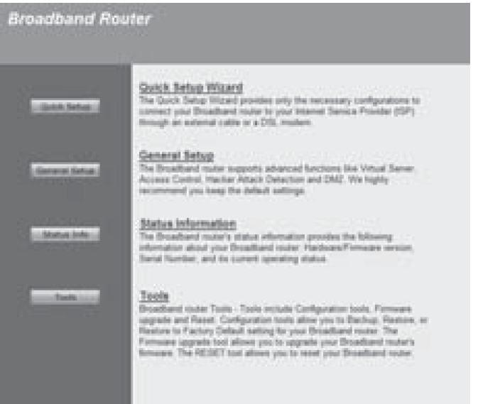
Router configuration utility
The default router confi guration wizard will now start. Time Zone
- Select the appropriate time zone.
- The Time Server Address fi eld allows you to enter the IP address of a time server to set the router clock automatically. The fi eld contains a default value, but can be changed if you wish to use a different time server.
- The Daylight Savings fi eld indicates whether the router will switch automatically between sum-mer time and winter time. Check the box Enable Function, and enter the dates for changing to summer time or winter time.
- Click [Next].
Broadband Type
Here you can enter the type of connection used by the router. Contact your Internet service provider if you are unsure which type of Internet connection you have.
- Select Cable modem if you have a cable modem or other type of Internet connection without a fixed IP address.
- Host name: Can be set to any name unless specifi ed by your Internet service provider.
The MAC address is automatically set to the MAC address of your cable modem. This should not be changed unless specifi ed by your Internet service provider. - Clone MAC address: This function is usually not required for default setup. This button can be used to specify the MAC address of the computer’s network card as the actual MAC address of the router.
- When your changes are complete, click [OK]. The router will then confi rm the changes. Click [OK].
- Close the window by clicking the cross in the top right corner.
- Select Fixed-IP xDSL if you have an xDSL or Ethernet connection with a fi xed IP address.
- IP address assigned by your service provider: Enter the IP address assigned by your Internet service provider.
- Subnet mask: Enter the subnet mask assigned by your Internet service provider.
- DNS address: Enter the DNS addresses assigned by your Internet service provider.
- Service provider gateway address: Enter the gateway address assigned by your Internet service provider.
- When your changes are complete, click [OK]. The router will then confi rm the changes. Click [OK].
- Close the window by clicking the cross in the top right corner.
- Select Dial-up xDSL (PPPoE) if you have an xDSL/FWA connection that uses PPPoE.
- User name: Enter the username assigned by your Internet service provider.
- Password: Enter the password assigned by your Internet service provider.
- Service name: Enter the service name assigned by your Internet service provider. If you have not been assigned a service name by your Internet service provider, this fi eld can be left blank.
- MTU (1400-1492): The router will propose 1492. You can accept this unless your Internet service provider recommends a different value.
Connection type
There are three options to choose from:
- Continuous – the router maintains a permanent connection to your Internet service provider.
- Connect on demand – the router only connects when necessary and disconnects itself after a set period of time (see Idle time).
- Manual – you activate the connection through the router yourself when you need it.
- Idle time: Specifi es the period of time after which the router will disconnect when it is not in use. This function is only used if the Connection type is set to Connect on demand.
- When your changes are complete, click [OK]. The router will then confi rm the changes. Click [OK].
- Close the window by clicking the cross in the top right corner.
- Select PPTP if you have a connection of this type.
- [NB: This connection is rarely used in Scandinavia.]|
- WAN Interface Settings: Set the router to obtain an IP address automatically, or enter the IP address, subnet mask and gateway if these have been assigned to you by your Internet service provider.
- PPTP Settings: Enter the information assigned by your Internet service provider in the appropriate fi elds.
- When your changes are complete, click [OK]. The router will then confi rm the changes.
Click [OK]. - Close the window by clicking the cross in the top right corner.
Securing a wireless network
If you are using the router’s wireless functionality, the network must be secured against unauthorised access by enabling one of the router’s built-in security features. This protects authorised network users against unauthorised access from the outside.
The router can use one of the following security features:
- WEP
- WPA pre-shared key
- WPA RADIUS
All computers that connect wirelessly to the router must use the same type of security as the router. It is therefore important to select a security method supported by all the network cards on the network. For more information on this, see the user guide for the individual network cards on the network. For additional security, the MAC Address Filtering function can be used. See section 2.3.4 for information on this. Configuration of the various security features is described in the following sections.
Configuring WEP
- Click [General Setup].
- Click [Wireless], then [Security Settings].
- Under Encryption, select WEP.
- Under Key Length, select the encryption strength. You can select either 64-bit or 128-bit.
For greatest security, 128-bit is recommended. - Under Key Format, select the format for entering security codes. You can select either HEX
(digits and/or letters from A to F) or ASCII (letters and/or digits). - Under Default TX Key, select the security code to use as default.
- In the fields Encryption Key 1-4, enter up to four security codes. If you enter multiple codes, computers can access the network wirelessly by entering any one of them. The codes must comply with the format given in Key Length and Key Format. Both upper and lower case letters can be used.
- 64- bit HEX – 10 digits and/or letters from A to F
- 128-bit HEX – 26 digits and/or letters from A to F 64-bit ASCII – 5 letters and/or digits
- 128-bit ASCII – 13 letters and/or digits
- Click [Apply].
- Click [Continue] to change more settings or [Apply] to restart the router for the new settings to take effect.
Configuring WPA pre-shared key
- Click [General Setup].
- Click [Wireless], then [Security Settings].
- Under Encryption, select WPA pre-shared key.
- Under WPA Unicast Cipher Suite, select the type of encryption to use. You can select WPA(TKIP), WPA2(AES) or WPA2 Mixed. Note that all devices connecting to the network must support the encryption type.
- Click [Apply].
- Click [Continue] to change more settings or [Apply] to restart the router for the new settings to take effect.
WPA RADIUS
This type of security is for advanced users and requires a separate RADIUS server. WPA RADIUS is typically used in larger corporate networks, and is not recommended for private use. Documentation on configuring the router for WPA RADIUS can be found in the English manual on the CD provided.
Configuring MAC Address Filtering
All network devices have a unique code called the MAC address. Mac Address Filtering is an extra security feature that ensures that only network devices with MAC addresses approved by the router can connect to the wireless network.
- Click [General Setup].
- Click [Wireless], then [Access Control].
- In the MAC address fi eld, enter a MAC address.
- If necessary, enter a comment for the MAC address in the Comment fi eld.
- Click [Add] to add the MAC address to the list of approved addresses.
How to discover the MAC address of a wireless network card Windows® XP
- Click Start, then Control Panel, then Network and Internet Connections,
then Network Connections. - Double-click the icon for the wireless network connection, click the Support tab and then click Details…
- The value indicated for Physical address is the network card’s MAC address.
Windows® 2000
- Click Start, then Run. Type “cmd” in the fi eld and press Enter.
- Type “ipconfi g/all”.
- Locate the line with “Description…” followed by the name of the wireless network card. The value indicated for Physical address is the network card’s MAC address.
Windows® 98SE / ME
- Click Start, then Run. Type “winipcfg” in the fi eld and press Enter.
- Click the little arrow and select the wireless network card from the menu.
- The value indicated for Network card address is the network card’s MAC address.
Advanced setup
Advanced setup enables you to defi ne specifi c settings for your network’s security policy, data traffi c, etc. This requires specialised knowledge, including network technologies and security policies, and is only recommended for users with experience in these areas. These settings are not usually required for standard setup.
- Start your Internet browser (e.g. Internet Explorer®).
- Enter “http://192.168.2.1” in the browser’s address bar and press Enter.
- In the Username fi eld, type “admin”.
- In the Password fi eld, type “1234”.
- If you want this to be remembered next time you log on, check the box Remember password. Click [OK].
- Click the [General Setup] button.
System
The System menu contains settings for the time zone, password and remote access to the router.
Time Zone
- Select the time zone in the Set Time Zone menu.
- Enter the IP address of a time server in the Time Server Address fi eld. The fi eld contains a default value, but can be changed if you wish to use a different time server.
- Check the box next to Enable Function and set the start and end date for summer time in the Daylight Savings field.
- Click [Apply] to confirm the settings.
Password Settings
To change the password for access to the router, follow the steps below.
- Enter the current password in the Current Password field.
- Enter a new password in the New Password and Confirmed Password fields.
- Click [Apply] to confirm the settings.
Remote Management
Settings for remote access to the router configuration utility. Remote access allows the router to be configured from a computer via the Internet.
NB: If you enable remote access, it is essential that you change the default password for router access to a password of your choosing. See section 3.1.2.
- Check the box next to Enabled to enable remote access.
- In the Host Address fi eld, enter the IP address of the computer on the Internet that will have remote access to the router confi guration utility.
- Enter IP address 0.0.0.0 to give all computers remote access.
- Click [Apply] to confi rm the settings.
WAN
Settings for manual confi guration of the connection type. The settings are the same as those confi gured in Quick Setup. See section 2.2 (subsection WAN Type) for information on the various settings.
LAN
For setting the router’s IP address and confi guring its DHCP server.
LAN IP
- Enter the desired IP address for the router in the IP Address fi eld.
- Enter the subnet mask in the IP Subnet Mask fi eld.
- Click [Apply] to confi rm the settings.
3.3.2 DHCP Server
- In the Start IP fi eld, enter the fi rst IP address in the range that the DHCP server can allocate.
- In the End IP fi eld, enter the last IP address in the range that the DHCP server can allocate.
- If necessary, the router’s DHCP server can be disabled by selecting Disabled in the
DHCP Server fi eld. - Click [Apply] to confi rm the settings.
Wireless
Enable or disable wireless access to the router. By default, this function is enabled.
- Select Enable to enable wireless access to the router, or Disable to disable the function.
- Click [Apply] to confi rm.
Basic Settings
- In the ESSID fi eld, enter the name for the wireless network. This is the name that will be shown when Windows® displays a list of available wireless networks.
- AP, Band and Channel Number are advanced settings and should only be changed in special circumstances.
- Click [Show Active Clients] to view a list of wireless devices currently connected to the router.
Advanced Settings
This menu contains advanced settings for the wireless network. They require thorough knowledge of wireless networking technology and do not normally need to be changed. Documentation on these functions can be found in the English manual on the CD provided.
Security Settings
See section 2.3.
Access Control
See section 2.3.4.
QoS
- Reserve bandwidth for specifi c web applications.
- Limit bandwidth usage for specifi c web applications.
Quality of Service (QoS) is a function that allows the router to prioritise bandwidth usage so that specifi c services are always guaranteed a certain level. This can be very useful for services such as IP telephony, to ensure that call quality is not diminished when there is heavy network traffi c. QoS can also be used to impose a maximum limit on the bandwidth usage of certain applications.
To use Quality of Service, one or more rules must be set up to defi ne the bandwidth requirements for certain applications.
The router has no direct link to applications on the computer, so the only way to control the applications’ network traffi c is to confi gure rules regulating traffi c on the network ports used by the applications. You therefore need to know which network ports are used by an application before you can set up a Quality of Service rule. The ports an application uses can normally be found in the application’s written documentation or on its website.
QoS menu
The QoS menu contains a list of rules that have been set up. Every rule on the list has a priority (Priority). The rule with the highest priority is allocated bandwidth fi rst, and so on down the list. Network traffi c that is not covered by user-defi ned rules is allocated bandwidth last of all.
NB: If the total bandwidth allocated to user-defi ned rules exceeds the bandwidth the Internet connection can deliver, no bandwidth will be available for other applications.
Enable QoS – Enable Quality of Service. Check this box if you wish to use Quality of Service. Click [Apply] to confi rm.
Adding a QoS rule
- Click [Add].
- Enter a name for the rule in the Rule Name field. This could be the name of the application the rule relates to.
- Under Bandwidth, the first field allows you to select whether the rule will apply to incoming traffic (Download) or outgoing traffic (Upload). If you need to establish rules for both incoming and outgoing traffic, you must set up one rule for each.
- In the second field, enter the amount of bandwidth you wish to reserve. This must be given in kilobits per second (kbps).
- In the third field, indicate whether the bandwidth entered is a guaranteed minimum (Guarantee) or a maximum limit that cannot be exceeded (Max).
- In the Local IP Address field, enter the local IP addresses the rule will apply to. Enter a start address and end address in the fields. For example, 192.168.2.1-192.168.2.255 would represent all the computers on the network 192.168.2.xxx (where “xxx” is a number between 1 and 255)
- In the Local Port Range field, enter the local network ports the rule should apply to. If the application only uses a single port, enter it in this field. Otherwise a range of ports can be specified by using a hyphen. For example: 800-1000, which specifies all ports between 800 and 1000.
- In the Remote IP Address field, enter an IP address on the Internet, from which all traffic will be subject to the rule. Traffic not originating from this address will not be affected. It is not normally necessary to enter a value for this fi eld.
- In the Remote Port Range fi eld, enter one or more ports, from which all traffi c will be subject to the rule. Traffi c not originating from these ports and the address entered under Remote IP Address will not be affected. It is not normally necessary to enter a value for this field.
- Traffic Type – Choose between a range of predefined types of network traffic. If you select a type here, you do not need to enter a value for Local Port Range. The options are:
- None – No traffi c type is selected. Select this if a value has been entered for Local Port Range.
- SMTP – Outgoing email.
- HTTP – World Wide Web.
- POP3 – Incoming email.
- FTP – FTP server.
- Protocol – Select the network protocol the rule applies to. You can select either TCP or UDP. Information on the protocols used by an application can be found in the application’s documentation. If an application uses both protocol types, two QoS rules must be set up.
- Click [Save] to add the rule. Click [OK]. Click [Apply].
Moving a QoS rule
If a rule needs to be allocated higher or lower priority, it can be moved up or down the list.
- To select a rule, check the box next to it in the Select column.
- Click [Move Up] to give the rule higher priority or [Move Down] to give it lower priority.
- Click [Apply].
Deleting a QoS rule
- To select a rule, check the box next to it in the Select column.
- Click [Delete Selected].
- Click [OK] in the two boxes that appear.
- Click [Apply].
Deleting all QoS rules
- To select a rule, check the box next to it in the Select column.
- Click [Delete All].
- Click [OK] in the two boxes that appear.
- Click [Apply].
NAT (Network Address Translation) is a technology that allows multiple computers on a local area network to share the same external IP address. The way this works is that the router manages all the network traffic originating from the computers on the network and sorts incoming network traffic so it is redirected to the right computer. However, this may cause a problem for network traffic that is not initiated at the request of a computer on the local area network.
A typical scenario is when a computer on the local area network is set up as a server. In this case, a computer on the Internet would connect to the router’s external IP address. However, this network request does not indicate which computer on the local area network it is addressed to, and the router therefore has no means of knowing where to forward it. This is solved by setting up the router’s NAT function so that it forwards incoming network traffic on certain network ports to a specific IP address on the local area network.
Example: An FTP server is set up on a computer on the network with the IP address 192.168.2.100. FTP uses network port 21 by default. The router’s NAT function is set up to forward all incoming traffic on port 21 to IP address 192.168.2.100.
It may also be necessary to configure NAT for applications such as IP telephony, fi le sharing and online gaming to work properly. NAT can be configured in two modes: Port Forwarding and/or Virtual Server. These are described in the following sections.
Port Forwarding
Port Forwarding means setting up rules specifying the type of network traffi c to be redirected to a particular computer on the local area network.
NB: For Port Forwarding to work as intended, the computer that network traffi c is forwarded to must be confi gured with a static IP address. See section 3.6.3 for information on this.
- Click [General Setup]. Click [NAT]. Click [Port Forwarding].
- Check the box next to Enable Port Forwarding.
- Enter the IP address of the computer on the local area network to redirect to in the
Private IP field. - Specify the type of network traffic to redirect under Type. Select TCP, UDP or both (Both).
- The network traffic type depends on the type of application used on the computer that traffic is forwarded to. If necessary, see the application’s documentation for details on this.
- Enter the ports from which network traffic should be forwarded in the Port Range field.
- If you wish, enter a comment in the Comment field.
- Click [Apply].
You can edit the defined rules in the list at the bottom of the screen.
Delete a rule – Check the box next to the rule in the Select column. Click [Delete Selected]. Delete all rules – Click [Delete All].
Virtual Server
Virtual Server works in almost the same way as Port Forwarding. The only difference is that network traffi c arriving at an external network port can be forwarded to another network port on a computer on the local area network. This might be useful if you have a server set up on the local area network that does not use the default port.
Example: An FTP server is set up on a computer on the local area network with the IP address 192.168.2.100. This server does not use default port 21, but instead uses port 3015. Virtual Server can be set up to forward all incoming traffi c on port 21 to IP address 192.168.2.100 on port 3015. This means that users of the FTP server do not have to change the port number used by their FTP application to connect to the server.
NB: For Virtual Server to work as intended, the computer that network traffi c is forwarded to must be confi gured with a static IP address. See section 3.6.3 for information on this.
- Click [General Setup]. Click [NAT]. Click [Virtual Server].
- Check the box next to Enable Virtual Server.
- Enter the IP address of the computer on the local area network to redirect to in the Private IP field.
- Enter the port on the local area network to redirect traffi c to in the Private Port fi eld.
- Specify the type of network traffi c to redirect under Type. Select TCP, UDP or both (Both).
- The network traffic type depends on the type of application used on the computer that traffic is forwarded to. If necessary, see the application’s documentation for details on this.
- Enter the external ports from which network traffic should be forwarded in the Public Port fi eld.
- If you wish, enter a comment in the Comment field.
- Click [Apply].
You can edit the defi ned rules in the list at the bottom of the screen.
Delete a rule – Check the box next to the rule in the [Select] column. Click [Delete Selected]. Delete all rules – Click [Delete All].
Specifying a static IP address in Windows®
In certain circumstances it may be useful to ensure that one or more computers on the local area network always have the same IP address. This is particularly relevant when setting up NAT.
(See section 3.6.) This section describes how to confi gure a static IP address.
Specifying a static IP address in Windows® XP
- Click [Start]. Click [Control Panel].
- Click [Network and Internet Connections], then [Network Connections].
- Double-click [LAN Connection]. Click [Properties].
- Double-click [Internet Protocol (TCP/IP)].
- Check Use the following IP address and enter the desired IP address in the IP address fi eld.
- Click in the Subnet mask fi eld. The mask 255.255.255.0 is entered automatically. Click [OK].
- Click [OK] to close the window. Click [Close] in the last window.
Specifying a static IP address in Windows® 2000
- Click [Start], then [Settings] and [Dial-up and Network Connections].
- Double-click [LAN Connection]. Double-click [Internet Protocol (TCP/IP)].
- Check Use the following IP address and enter the desired IP address in the IP address fi eld.
- Click in the Subnet mask fi eld. The mask 255.255.255.0 is entered automatically.
- Click [OK] and close the Local Area Connection Properties dialog box by clicking [OK].
Specifying a static IP address in Windows® 98SE/ME
- Right-click [Other Computers] on the desktop. Click [Properties].
- Double-click [LAN Connection]. Click [Properties].
- Find the protocol for the computer’s network card that begins with “TCP/IP ->”. Double-click it.
- Select the IP address tab. Check Enter an IP address and enter the desired address in the
IP address fi eld. - Enter the mask 255.255.255.0 in the Subnet mask field. Click [OK].
- Click [OK] in the last window.
- Restart your computer.
Firewall
The router’s built-in firewall can be configured to protect against commonly occurring hacker attacks. It is also possible to block or authorise specific MAC addresses and/or IP addresses, and to block access to certain websites on the Internet.
- Select Enable to enable the firewall on the router, or Disable to disable the function.
- Click [Apply] to confirm.
Access Control
Configuration of the MAC addresses that can access the router. This works in the same way as Access Control described in section 2.3.4, but here it also applies to the cabled network as well as traffi c from the Internet.
- Check the box next to Enable MAC Filtering to enable the function.
- In the Client PC MAC address fi eld, enter a MAC address.
- If necessary, enter a comment for the MAC address in the Comment fi eld.
- Select Deny (to block the address) or Allow (to allow the address).
- Click [Add] to add the address to the list.
- Click [Apply] to confirm.
URL Blocking
Block particular addresses on the Internet to prevent them from being accessed by computers on the local area network.
- Check the box next to Enable URL Blocking to enable the function.
- Enter an Internet address in the fi eld URL / Keyword and click [Add] to add it to the list.
DoS (Denial of Service)
Block commonly occurring hacker attacks.
- Select the types of hacker attack to block by selecting them on the list.
- Click [Apply] to confirm.
DMZ
If a computer on the local area network is running an application that is incompatible with NAT and firewalls, the computer can be configured to bypass these functions in its communication.
- Check the box next to Enable DMZ to enable the function.
- Specify whether your Internet connection has a dynamic or static IP address in the Public IP
- Address fi eld. If the IP address is static, specify the address in the Static IP field.
- Specify the IP address of the computer on the local area network whose communication will bypass NAT and firewall in the Client IP Address field.
- Click [Apply] to confirm.
Troubleshooting
- I cannot connect to the router when I type http://192.168.2.1 in my browser.
- Check that the originating computer is connected to the router’s wireless network.
See section 2.2. - Check that the originating computer is configured to be automatically allocated an IP address. See section 2.1.
- If necessary, try connecting the computer directly to port 1 on the router using a network cable.
The router cannot be detected by any wireless devices in the vicinity.
- Check that the “WLAN” LED on the router is on.
- Check that the router is within range of the wireless devices. Try repositioning the router or the wireless device trying to connect to it. The number of walls and ceilings, their thickness and materials, are all factors that affect the strength of the wireless signal.
- Check that the wireless devices are connected to the correct wireless network. See the documentation for the wireless devices for information on this.
Unable to connect to the router from a wireless device.
Check that the security settings are appropriate for the wireless devices trying to connect to the router. See section 2.3 and the documentation for the wireless device for information on security settings.
The Internet connection is unstable when using PPPoE.
Try changing the MTU value to 1440 (see section 2.2), or contact your Internet service provider for further information.
If you need further help or assistance in connection with your Sandberg product, you can see details about this on the penultimate page of these instructions.
Sandberg G54 Wireless Router User Manual
FAQs
Which wireless standards are supported by the G54?
Wi-Fi 6 (802.11ax) is supported for increased speed and efficiency.
What is the G54 router’s fastest speed?
1800 Mbps (2.4GHz and 5GHz bands combined).
Are there any gigabit Ethernet ports on it?
Yes, four Gigabit LAN ports are included for wired connectivity.
Does the G54 have three or two bands?
Dual-band (2.4 GHz + 5 GHz) for best results.
Is MU-MIMO supported?
Indeed, MU-MIMO technology makes it possible for several devices to connect effectively.

